Open hardware · Open source
 A versatile emulation platform on a single board.
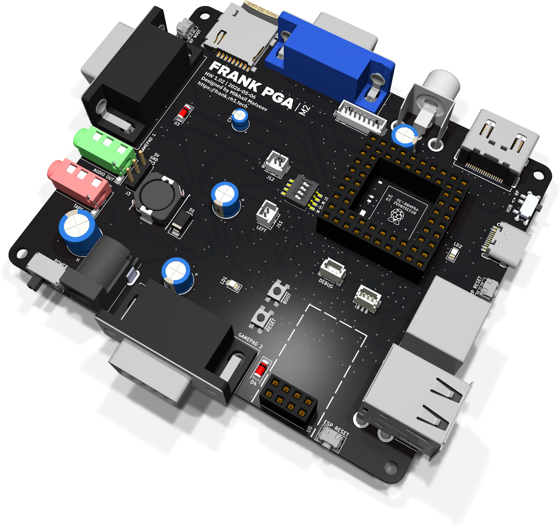
FRANK runs on a Raspberry Pico (RP2040 / RP2350) and brings classic gaming and computing back to life: DOOM, NES, SNES, Sega Genesis, NEC PC Engine, MSX, Apple II, ZX Spectrum, Atari 800, IBM PC / i386, SCUMMVM and more. HDMI, VGA, composite video, USB keyboards and mice, game controllers — out of the box. Easy to use, opinionated to configure, fully open.
One board, many machines
Switch between ZX Spectrum, NES, Atari 800 and the IBM PC family. Program and game images live on your MicroSD card, not on a ROM module.
Multiple video outputs
HDMI for modern TVs, VGA for older monitors, composite for the original CRT — pick the output that matches the era you are running.
FRANK OS
A desktop operating system for the RP2350 microcontroller. Windowed GUI with a mouse, terminal, file manager and apps — all running in 520 KB of SRAM. Window management, menus, dialogs, and preemptive multitasking, Windows 95-style, on a chip the size of a coin.